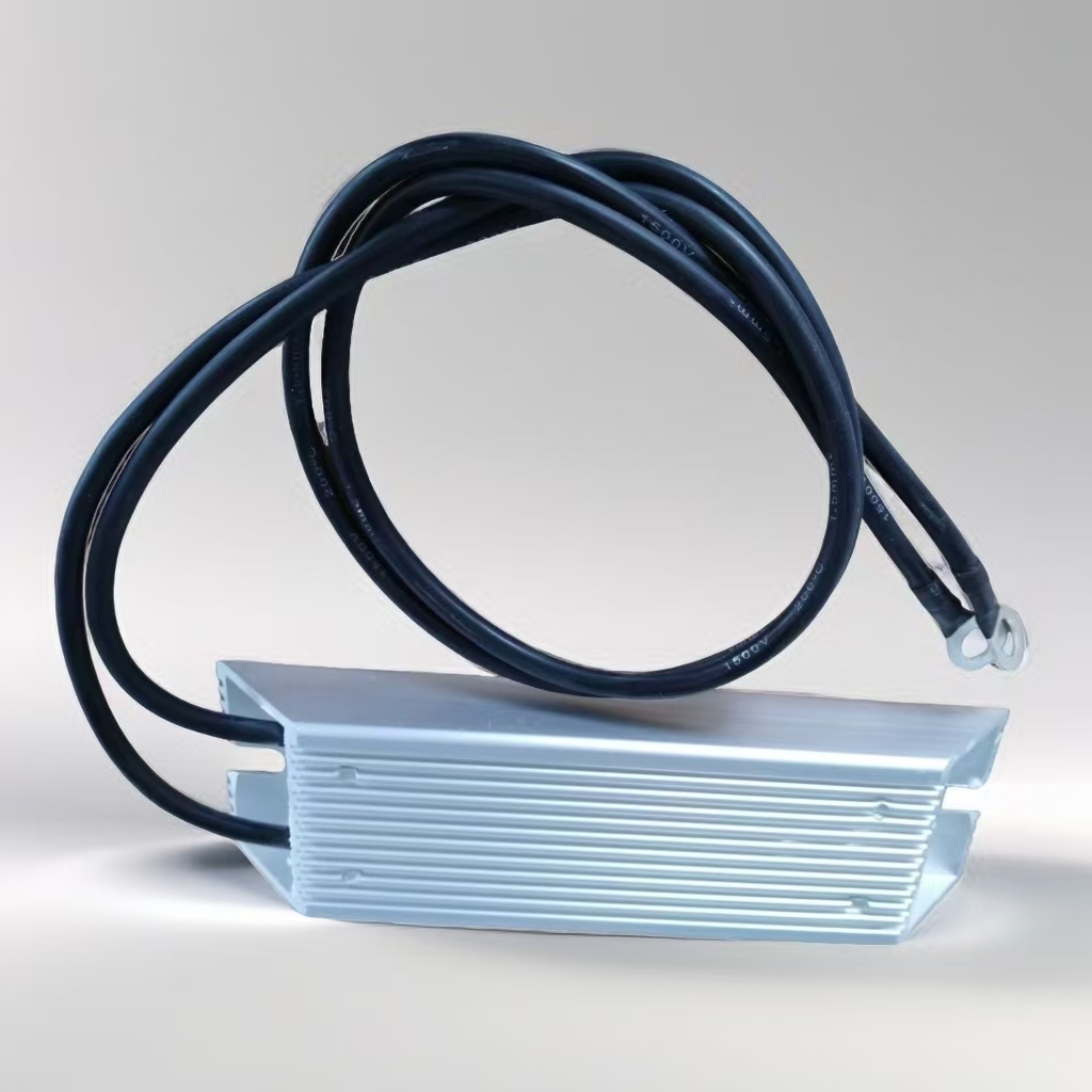
100W Trapezoidal Efficient thermal management dynamic aluminum housing resistors for electric motors
50W-6KW
100W Trapezoidal Efficient thermal management dynamic aluminum housing resistors for electric motors
Product Description:
The resistor's core components are constructed from insulating and high-temperature resistant materials, providing a robust framework.
The lead wire: Grid braided layer TPE protective layer - Grid braided layer + TPE layer provide double protection for the wires, reducing the erosion of light, heat, moisture, low temperature, acid and alkali gases, and damage from external mechanical forces, ensuring safe operation of the wires
The aluminium shell: The guide groove design improves heat dissipation. The guide groove is formed by a special process, and the hot air will flow along the groove to dissipate the heat in a short time.
High temperature resistant braided wire/beautiful appearance Tight packaging/conducive to high-temperature resistant overload protection.
What is the function of the brake resistor? It is mainly used in mechanical systems where the inverter controls the motor to stop quickly, helping the motor to convert the regenerative electrical energy generated by the rapid stop into heat energy.
- Protect the inverter from failures and damage caused by the motor's regenerative electrical energy.
- Ensure that the power supply network is stable and the regenerative electrical energy is converted into heat energy. The power supply network will not cause voltage fluctuations in the power grid, ensuring the smooth operation of the power supply network.

| Rated power | Overall | Dimension(mm | Adaptive variable Power(KW) |
Matching Electricity old value(R |
||||||
| L | L1 | W | H | E | lead wire | Line length | ||||
| 50-60 | FigureA | 115 | 98 | 40 | 20 | 350 | 0.4-0.75 | 750 | ||
| 80 | 140 | 123 | 40 | 20 | 1 | 350 | ||||
| 100 | 165 | 148 | 40 | 20 | 1 | 350 | 1.5 | 390 | ||
| 120 | 190 | 173 | 40 | 20 | 1 | 350 | ||||
| 150 | 215 | 173 | 40 | 20 | 1 | 350 | ||||
| 200 | 165 | 147 | 60 | 30 | 1.5 | 350 | ||||
| 300 | 215 | 197 | 60 | 30 | 1.5 | 350 | 2.2-3.7 | 150 | ||
| 400 | 285 | 247 | 60 | 30 | 1.5 | 350 | ||||
| 500 | 335 | 317 | 60 | 30 | 1.5 | 350 | 5.5 | 100 | ||
| 800 | 400 | 382 | 60 | 30 | 2 | 350 | 7.5 | 75 | ||
| 800 | FigureB | 400 | 382 | 61 | 59 | 40.5 | 2.5 | 350 | ||
| 1000 | 400 | 384 | 50 | 107 | 30 | 2.5 | 350 | 11 | 40-50 | |
| 1200 | 450 | 434 | 50 | 107 | 30 | 2.5 | 350 | |||
| 1500 | 485 | 470 | 50 | 107 | 30 | 4 | 350 | 15 | 40 | |
| 2000 | 550 | 532 | 50 | 107 | 30 | 4 | 350 | 15-18.5 | 20-40 | |
| 2500 | 550 | 532 | 50 | 107 | 30 | 4 | 350 | |||
| 3000 | 550 | 532 | 50 | 107 | 30 | 4 | 350 | |||
| 4000 | 700 | 686 | 50 | 107 | 30 | 4 | 350 | 18.5-22 | 20-32 | |
Dynamic braking resistors (DBRs) are an essential component in variable frequency drives (VFDs) to manage the energy generated during the motor's deceleration. When a VFD slows down a motor, the motor can act as a generator, producing energy that needs to be dissipated to prevent damage to the system
Aluminum is often chosen for the construction of DBRs due to its excellent thermal conductivity, which allows for efficient heat dissipation. It's also lightweight and corrosion-resistant, making it suitable for various industrial applications.
If you're looking to implement a dynamic aluminum braking resistor for your VFD, you'll need to consider factors such as the resistor's power rating, resistance value, and cooling requirements to ensure it matches your system's specifications and the specific braking demands of your application


