-
 Integrated Current Sensing Busbar for Inverter and Motor Control Systems This integrated current sensing busbar combines high-conductivity copper pathways with a built-in precision shunt, delivering accurate current measurement and reliable power distribution in a single compact unit. Designed specifically for industrial motor drives and inverter systems, it simplifies wiring, saves space, and enhances real-time monitoring. ✅ Key Advantages Accurate current sensing – Built-in shunt provides real-time feedback for control systems Compact integration – Combines conduction and detection functions in one structure High reliability – Withstands thermal stress and high current loads in demanding environments Improved safety – Enables overload protection and better energy efficiency Customizable design – Dimensions, resistance, and terminal t...
 -
Solutions for Inductive Noise Mitigation
-
Function Setting ACLT-38100 Function Setting 1. Load power setting: 0-1000KW continuously adjustable, simulating communication equipment of various powers. 2. Load time setting: 0-99 hours continuously adjustable, set according to maintenance needs. 3. Load minimum voltage alarm setting: set according to maintenance needs. 4. Load maximum voltage alarm setting: set according to maintenance needs. 5. Parallel setting function: up to 9 units can be connected in parallel and work at the same time. 6. Built-in storage function: continuously record the test data of the last three hours, simple and convenient operation. 7. Software analysis function: use Chinese Windows operating environment, Chinese culture, graphical and control system, and automatically generate test reports. Application field Widely used in communications, civil aviation, banking, securities, railway ...
-


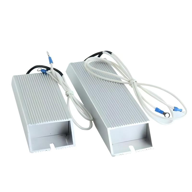
We provide custom Air coils and shunt resistor&braking resistor with expert production management, ensuring smooth operations and helping you excel in the market.

Copyright©Changzhou Yuansheng Technology Co.,ltd .All Rights Reserved/Sitemap